Micro Gas Turbine Design
Design a single-shaft turbojet end to end, live with the instructor, over seven half-day sessions.
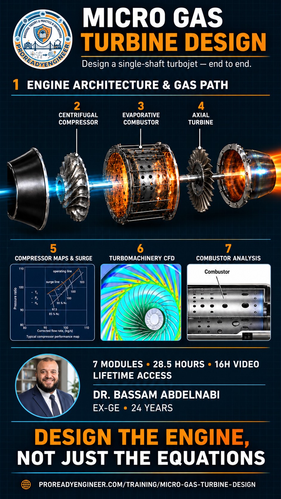
This is the live edition of our Micro Gas Turbine Design programme: the same curriculum delivered to a national jet-engine development team, taught in real time over seven consecutive business days. One reference engine runs through every session, so the compressor you size on day two is the compressor the turbine has to match on day four. You bring your questions to the instructor as the design unfolds, and you keep lifetime access to the complete recorded course after the live days end.
The 7-Day Arc
Engine Architecture: Single-Shaft Layout & Material Philosophy
Walks the complete gas path of a single-shaft turbojet station by station, from ambient through the inlet, centrifugal compressor, evaporative tube combustor, axial turbine and converging nozzle. Every component is covered for function, interface and failure mode alongside the material behind it: Ti-6Al-4V impellers, IN713 turbine parts, Hastelloy X liners and Si3N4 ceramic bearings. Closes with the manufacturing route for each part plus the shaft, casings, ECU and fuel system that tie the engine together.
- Gas path station numbering convention (0-1-2-3-4-5-8)
- Inlet design considerations
- Centrifugal compressor: impeller, diffuser, volute
- Evaporative tube combustor: working principle
- Axial turbine: NGV and rotor
- Converging nozzle
- Main shaft, bearings, and casings
- ECU and fuel system overview
- Material selection: Ti-6Al-4V, IN713, Hastelloy X, Si3N4 ceramics
- Manufacturing process overview per component
- Identify every component in a single-shaft turbojet
- Understand its function and interface
- Explain the material selection rationale for each
Centrifugal Compressor: Aerodynamics, Design & Performance Map
Builds centrifugal compressor aerodynamics from the inlet velocity triangle through the Euler work equation, tip speed and pressure ratio scaling, slip factor by the Wiesner correlation, and vaned versus vaneless diffuser pressure recovery. The second half moves onto the performance map: corrected axes, speed lines, surge and choke, and where the operating line and surge margin sit between them. Worked examples run on the reference 80 mm impeller at 80,000 RPM delivering a pressure ratio of 3.5.
- Centrifugal compressor stage overview
- Inlet velocity triangle: absolute and relative velocities
- Euler turbomachinery equation: work input
- Impeller tip speed and pressure ratio relationship
- Slip factor: Wiesner correlation
- Vaneless and vaned diffuser comparison
- Pressure recovery and diffuser efficiency
- Compressor map: pressure ratio vs mass flow
- Surge line, choke line, and operating line
- Stall inception mechanisms
- Design point and off-design behaviour
- Understand centrifugal compressor aerodynamics from inlet velocity triangles through to diffuser exit
- Read and interpret a compressor performance map
Evaporative Tube Combustor: Design Principles & Fuel Delivery
Covers the evaporative tube combustor: how fuel vaporises inside heated tubes, why that approach beats a pressure-jet atomiser at small engine scale, and how the primary, secondary and dilution zones split the incoming air. Participants calculate fuel-air ratio and equivalence ratio for the primary zone against the Jet-A1 stoichiometric FAR of 0.0667, and set the combustor pressure drop budget. Ends with fuel manifold and tube arrangement, spark and glow plug ignition, and hot start causes and diagnosis.
- Evaporative vs pressure-jet atomiser comparison
- Fuel vaporisation mechanism in heated tubes
- Primary zone stoichiometry: equivalence ratio calculation
- Secondary zone: CO burnout and dilution
- Dilution zone: pattern factor and TET shaping
- Stoichiometric FAR for Jet-A1 = 0.0667
- Primary zone FAR target: φ ≈ 1.0
- Fuel manifold and tube arrangement
- Combustor pressure drop: total and cold
- Ignition system: spark plug and glow plug types
- Hot start causes and diagnosis
- Understand the operating principle of an evaporative tube combustor
- Calculate air split, equivalence ratio, and fuel-air ratio for the primary zone
Axial Turbine: Aerodynamics, Blade Loading & Structural Integrity
Takes the single-stage axial turbine from NGV and rotor aerodynamics through velocity triangles, degree of reaction, stage loading and flow coefficient, and Euler work for zero exit swirl. The structural half covers disc centrifugal stress with the Lamé equations, the SF >= 1.5 requirement on rotating parts, LCF life by the Coffin-Manson approach and HCF screening on a Campbell diagram. Material limits are anchored to IN713 at 950 C turbine inlet temperature.
- NGV and rotor function: nozzle and blade row aerodynamics
- Velocity triangle at rotor inlet and exit
- Degree of reaction: 50% reaction design
- Stage loading coefficient ψ = ΔCw/U
- Flow coefficient φ = Ca/U
- Euler work for zero exit swirl: W = U × Cw1
- Blade profile types: impulse vs reaction
- Turbine disc centrifugal stress: Lamé equations
- Safety factor requirement: SF ≥ 1.5 for rotating parts
- LCF life: Coffin-Manson approach
- HCF: Campbell diagram for blades
- Material temperature limits: IN713 to 950°C TIT
- Understand axial turbine stage aerodynamics
- Draw NGV and rotor velocity triangles
- Calculate stage loading and identify structural failure modes
Compressor Map Generation & Surge Margin Analysis
Explains how a compressor map is generated on a test rig and how to read it: corrected pressure ratio and mass flow axes, speed lines, the surge line, and the distinction between rotating stall and full surge. The working skill is surge margin, SM = (PR_surge - PR_op)/PR_op, and the >= 10% requirement for small turbojets. Also covers how a TET change and inlet distortion move the operating and surge lines, what casing treatment buys, and why margin collapses during a throttle transient.
- How compressor maps are generated: test rig methodology
- Map axes: pressure ratio vs corrected mass flow
- Speed lines: corrected speed definition
- Surge line: physical mechanism
- Stall line: rotating stall vs surge distinction
- Operating line construction from cycle model
- Surge margin definition: SM = (PR_surge - PR_op)/PR_op × 100%
- Required surge margin: ≥10% for small turbojets
- Effect of TET change on operating line
- Effect of inlet distortion on surge line
- Casing treatment: slot and groove types
- Throttle transient: why surge margin reduces during acceleration
- Read and interpret a centrifugal compressor performance map
- Calculate surge margin
- Identify dangerous operating conditions
CFD Fundamentals & Application to Turbomachinery Components
Runs the CFD workflow for turbomachinery end to end: geometry, mesh type, boundary conditions, solver and post-processing. Covers y+ and near-wall resolution, choosing between k-epsilon and k-omega SST for compressors, periodic boundaries for blade passages, and frozen rotor versus mixing plane interfaces, then applies them to a compressor case with inlet total conditions and exit static pressure. Ends on validation against 1D meanline and test data, the errors that produce converged but wrong answers, and where ANSYS CFX, StarCCM+ and OpenFOAM fit.
- CFD workflow: geometry → mesh → BCs → solver → post-processing
- Mesh types for turbomachinery: structured, unstructured, hybrid
- y+ concept: wall distance and turbulence model requirements
- Turbulence models: k-ε vs k-ω SST: which to choose for compressors
- Periodic boundary conditions for blade passages
- Frozen rotor vs stage mixing plane interface
- Compressor simulation setup: inlet total conditions, exit static pressure
- Key outputs: total pressure ratio, isentropic efficiency, velocity vectors
- Validation: comparing CFD to 1D meanline and test data
- Common errors: poor mesh quality, wrong BCs, convergence without accuracy
- Introduction to ANSYS CFX, StarCCM+, and OpenFOAM for turbomachinery
- Understand the CFD process for turbomachinery flows
- Set up a RANS simulation correctly
- Interpret and validate results
Combustor Design Analysis: Heat Release, Liner Cooling & Fuel Scheduling
The analytical follow-on to the combustor design session: heat release rate from FAR and mass flow, combustion efficiency, and pattern factor with its target below 0.15 and its direct effect on turbine blade life. Covers dilution hole sizing to shape the TET profile, liner cooling by film, convective and transpiration routes, material selection between Hastelloy X and Nimonic 75, and evaporative tube flow matching to 2%. Closes with start fuel scheduling from propane ignition to main fuel, and hot-start diagnosis from the EGT trace.
- Heat release rate calculation from FAR and mass flow
- Combustion efficiency definition and measurement
- Pattern factor: definition, measurement, target <0.15
- Effect of pattern factor on turbine blade life
- Dilution hole sizing to achieve target TET profile
- Liner cooling: film cooling, convective cooling, transpiration
- Liner material selection: Hastelloy X, Nimonic 75
- Evaporative tube flow matching: tolerance ≤ 2%
- Fuel scheduling during start: propane ignition → main fuel
- Fuel schedule design: flow vs time vs temperature
- Hot-start diagnosis: EGT spike causes and corrective action
- Combustor CFD for reacting flow: simplified overview
- Analyse combustor performance
- Calculate heat release rate, pattern factor
- Design a fuel schedule for the start sequence
Same hours every day
Four teaching hours with a 10-minute break between each, keeping focus high and fatigue low over seven consecutive business days (weekends off). Sessions stream live for all four time zones below.
Times are for this cohort’s dates, with each country’s own daylight-saving rules applied.
Live Cohort Pricing
One price per seat, and the complete recorded course is included, so the material stays with you for good after the live days end.
Your seat covers all seven live sessions plus lifetime access to the complete recorded course: every video, design calculator, interactive tool and quiz. Register with no payment to hold your seat, then pay online or by invoice.
Your seat includes live instructor-led training across all seven design modules, direct access to the instructor as the reference engine takes shape, and the complete recorded course to revisit any derivation afterwards.
This cohort is designed to take you through a real design sequence: the architecture and materials on day one become the compressor you size on day two, the combustor you analyse on day seven: one engine, carried end to end.
This is not a lecture series. You work a complete engine design with an instructor who has delivered this programme to a national jet-engine development team.
Seven Live Sessions with Bassam Abdelnabi
Four focused hours a day over consecutive business days, taught in real time by the engineer who built and delivered this programme.
Direct Q&A During the Course
Ask your specific questions as each design decision is made, and connect the material to your own engine or project.
Full Recorded Course Included
Lifetime access to the complete on-demand edition (all seven modules, 16 hours of recorded video, slide decks and updates) in your own browser account.
Design Calculators & Interactive Tools
The four design calculators and two interactive tools used in the sessions, so you can rerun every sizing decision on your own numbers.
One Reference Engine, End to End
One reference engine runs through every session: the compressor you size in one module is the compressor the turbine has to match in another.
Three Verifiable Credentials
Your Certificate of Attendance, with contact hours and PDH, is issued when your full attendance is recorded and is available only to live attendees. Complete every module for the Certificate of Completion, and you become eligible for the instructor-examined Certificate of Verified Competency. All three are digitally signed and publicly verifiable.
For teams enrolling multiple engineers, contact ProReadyEngineer for group registration options.
Bassam Abdelnabi
Founder of ProReadyEngineer. 19+ years in gas-turbine combustion and test engineering, with multiple patents in gas-turbine combustion and emissions reduction. This programme was built for and delivered to a national jet-engine development team, and the live cohort teaches it the same way: one real engine, every decision worked through with its numbers. See reviews in the Testimonials section on proreadyengineer.com.
The course is built around field-grade design decisions, not textbook theory. Every session answers "what do you size, check and verify next" on a machine that has to run, not "what does the textbook say."
- Propulsion & Turbomachinery Engineers
- UAV / Small-Turbojet Developers
- Combustion & Test Engineers
- Graduate Engineers & Researchers
- Gas Turbine Enthusiasts
An engineering background helps, but every derivation is built from first principles on the reference engine. You'll leave able to size, check and analyse a small turbojet end to end.
Reserve your seat for the November 2, 2026 cohort
Registration is open for this cohort.
Three credentials, from attending to being examined in person.
Each is issued in your name, digitally signed, publicly verifiable by QR code or credential ID, and ready to add to your LinkedIn profile in one click. They differ in what they attest — attendance, completion, or examined competency — and in who did the attesting.

Certificate of Attendance
Live cohortFor attending the live, instructor-led course in full. It records your attendance and lists the topics covered and the professional development hours — a clean record for your CPD or PE renewal. It does not assess your knowledge; that is what the two stronger credentials do.
- Issued and emailed when the instructor records your attendance
- Contact hours and PDH stated on the certificate
- Unique credential ID and QR code; anyone can verify it online
- Add to LinkedIn profile and share buttons built in

Certificate of Completion
IncludedIssued automatically, with no request and no wait, the moment you have completed every lesson and passed every module evaluation and mastery check at the 80% threshold. It states exactly that, so it means something.
- Generated and emailed the instant the last requirement is met
- Programme, hours and modules spelled out on the certificate
- Unique credential ID and QR code; anyone can verify it online
- Add to LinkedIn profile and share buttons built in

Certificate of Verified Competency
Instructor examined · $300The credential a hiring manager can trust. After the course, you sit an advanced written examination and then a 60-minute live, one-on-one oral examination with the instructor: questions without notice, design cases not covered in the material, reasoning out loud. A pass issues a certificate signed by the instructor, attesting that you were examined in person and demonstrated a verified command of every key principle of the subject, each one listed on the certificate.
- Prerequisite: the Certificate of Completion
- Advanced written examination at analysis level, 80% pass mark
- 60-minute oral examination by video, scheduled around your time zone
- Signed and issued only by the instructor after the examination
- One complimentary re-examination if mastery is not shown the first time
Every certificate is signed with a cryptographic key; the verification page checks the signature and the file hash, so an altered name or date is caught.
Scan the QR code or type the credential ID at proreadyengineer.com/verify to see the holder, the course and exactly what was attested.
"Add to profile" pre-fills the Licenses & Certifications form; "Share" posts the verification page, which shows the certificate itself.
Specimens above are marked SAMPLE and were not issued to anyone. Each certificate attests to what it describes — attendance, completion, or examined competency; none is a professional engineering licence.
Independence notice: This independent ProReadyEngineer course is based on established public engineering and regulatory sources, original ProReadyEngineer teaching tools, and the instructor’s professional experience. It contains no OEM or other third-party confidential or proprietary information and is not affiliated with or endorsed by any OEM.